Whereabouts Clock: New Clock Mechanism
When I made the first mechanism of the Whereabouts Clock I utilized sail winch servos to get a motion that was at least 360 degrees. Most RC servos are limited to about 180 degrees before they hit a physical limit. I always wanted to create a clock with motors that weren't limited in the number of rotations, such as a stepper motor.
However, stepper motors don't retain positional accuracy after a power loss. The motor drivers only know "left" or "right" and a number of steps. If the motor is moved, or power is lost, it has no idea where the motors are any longer. In most control systems using stepper motors there are limit switches that are triggered to "home" the motors to a known position.
Also, the Arduino Uno is limited in the number of IO pins. Most stepper motor control requires at least 4 pins and additional lines for motor enable, micro switches for positioning, etc.
A while back I purchased an Arduino Mega and a six-pack of 28BYJ48 stepper motors and ULN2003 motor drivers. These motors are very common and inexpensive to purchase from Amazon, etc.: https://tinyurl.com/3d3m9abb

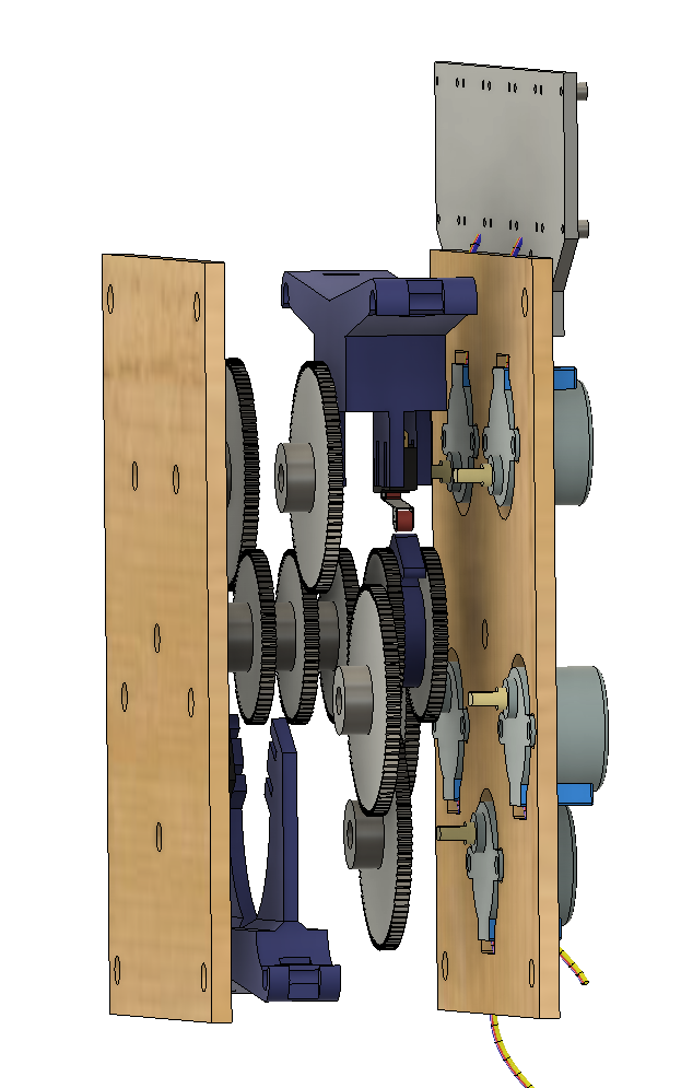
I attempted to retrofit the servo-controlled board, but eventually, it made sense to scrap the wood plates and just 3D print new components. I retained all the gears and brass shafts from the original, but 3D printed new plates, micro-switch holders, and positioning tabs. I also printed a bracket to hold each motor driver PCB. Here's a rendering from Fusion 360 so you can see how it generally all lines up:
I'm quite proud of the new Arduino code as well. Just like before the Arduino joins the home network at startup, but then it needs to home each motor by touching the micro switches. The motors rotate in one direction until the switch is triggered. It moves past the switch trigger location and then reverses until it touches coming from the other direction. The home location is in between the two touch points as calculated by the number of steps that the motor traversed. In this rendition, I'm also able to drive more than one motor at a time. There is a value in the code that defines the number of motors to simultaneously move. The more motors that move at once, the more current is needed from the power supply, so I keep this conservatively at 2 motors. This draws about 0.5 Amps at 5 Volts when running. Also, the specific motors to run are chosen at random and once a motor stops, another motor is allowed to start. It's a pretty cool system.
Also, I wanted to add a bit of random motion to the clock. It's known how many steps to complete a full revolution of the hands, and each position is a division of 12. There is a bit of code that is triggered when a hand move is needed that randomly injects either a direct move to the location, a reverse move, or even an extra turn left or right in the motion to get to the final location. The results are very cool.
Overall, I'm quite happy with this new version of the clock. I hope that Life360 continues to allow access to the location API.
Thanks for reading!


Comments
Post a Comment